Plc Circuit Diagram Example
Below is an input card and ladder logic diagram that shows how to connect an ac input card. To look many plc ladder diagram is better for learn plc programming.
 Micro820 Plc Wiring Diagram Diagram, Wire, Dca
These controllers can automate a specific process, machine function, or even an entire production line.

Plc circuit diagram example. Than we can say the old technology is still now used. The purpose of a plc was to directly replace electromechanical relays as logic elements. Developing the plc program example is a process that can be clearly defin.
Figure 5 below shows a schematic diagram for a plc based motor control system, similar to the previous motor control example. It includes a lot explination and a lot of great power and control circuit diagrams. But, the input of the delta & mitschibushi plc is represented by ‘x‘ and output represent by ‘y‘.
We will apply the five steps to a plc example program development of a sorting station. In the normal state, push button 1 is open and push button 2 closed. A programmable logic controller (plc), is a ruggedized computer used for industrial automation.
Above figure does not show limit switch because it depends on external interlock like say level switch, flow switch, pressure switch etc… depending on application. The rung becomes false and an output action does not occur Here is siemens s7200 plc rpgramming examples.(1) control requirementsmotors m1, m2, m3 three drive belt conveyor.press the start button sb1, start the order of m1, m2, m3, the interval of 3s.press the stop button …
Before using input or output, firstly you should be familiar with the input or output rules for writing. Plc ladder diagram program example for running motor: In ab, abb, and siemens plc, the input is represented by ‘i‘ and output is represented by ‘q‘.
In the normal state, push button 1 is open and push button 2 closed. But this time i am using only two switches s1 and s2 and one load which is going to be the 110/220vac light bulb. In the ladder diagram program, the switches are considering as inputs and load are considering as coil or output.
Another great example of how to use a plc for star/delta start of an ac motor is example #5 in the pdf file below. Plc circuit diagram in this article we will discuss about plc circuit diagram of input and output module of plc. The rung becomes true and an output action occurs (for example, a motor turns on) if the proper input conditions are not true:
You can learn the plc programming thoughts and ideas. Plc ladder diagram for single acting and double acting pneumatic cylinders. Later, iec standardized the plc programming languages including ladder programming in 1993.
That language seems like an electromechanical circuit schematic: Example #5 is on page 30. For this circuit we use one relay, one on delay timer, two push buttons and one lamp (+24vdc operated).
To jump to the previous example of motor control using latching logic click here. But, it does tend to become more complex. The following diagram shows a simple circuit to control a motor using a switch.
Plc can be considered as a large scale microcontroller for industries. Timer in plc ladder diagram on delay timer timing chart plc timer example. Pneumatic cylinder is advanced by pressing two push buttons simultaneously.
Plc input and output switch. Plc input cards rarely supply power, it means that needs external power supply for the inputs and sensors. It shows the components of the circuit as streamlined forms, and the power as well as signal links in between the devices.
Plc implementation of the circuit in figure 1 automation A programmable logic controller is a specialized computer used to control machines and processes. If interlock not required then simply remove the symbol from the diagram and connect with simple.
Collection of click plc wiring diagram. The above figure shows the physical layout of motor starter however this would be designed through ladder logic in this plc tutorial. Therefore, let’s consider a simple example.
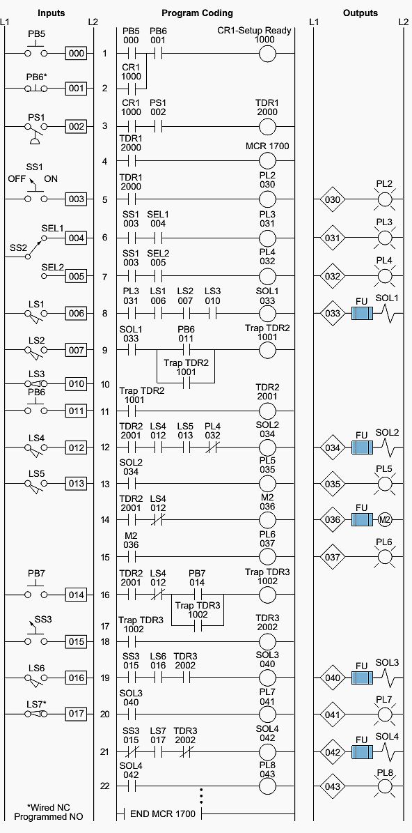
Figure 2 (see below) shows an example of a ladder diagram for a circuit that is used to start and stop a motor using push buttons. Ladder diagrams are essential in plc programming. In this example, the plc controller furnished with 8 (eight) inputs and 4 (four) outputs is used to switch and observe the procedure.
We can introduce a warning siren in order to let operators know that the motor is about to start. On off ladder logic example ladder logic example with toggle or flip flop function controlling water level in the plc ladder logic program example of motors with cooling in ladder logic. It therefore shares common terms with typical pcs like c.
Otherwise you use on delay timer. The connection of this plc module is described below. Below are two circuit diagrams showing both the sinking and sourcing inputs.
The program will use shift registers to track coloured parts down a conveyor and sort depending on colour into one of three locations. Star/delta start plc example (pdf) ladder diagram for dol direct on line motor starter How to write plc ladder program using a ladder diagram?
A wiring diagram is a streamlined traditional photographic representation of an electric circuit. Circuit diagram of the plc based staircase light control system: Given diagram shows the distinctive cabling essential to implement the process control arrangement by means of a fixed plc regulator.
Now that we’ve grasped the concept of the fail safe stop input let’s move on to the motor control ladder logic programming example. The ladder diagram graphical programming language is standardized by the plcopen organization, and thereby the symbols used in ladder diagrams.since ladder logic is a graphical programming language, the plc programs written in ladder logic are a combination of ladder logic symbols. Here we discuss about plc pneumatic circuit control with different examples.
It is always easier to understand pc programming with the help of example rather than tons of theory. This circuit depends on timer setting, if you use multifunction timer. Plc input module block diagram plc input module circuit diagram it is clear form the above figure that the input module is consist of two section one is power section while the other is logical section, which are electrically isolated from each other.
So for any plc input that is intended to stop the motor we need to.… wire the motor stop signals normally closed and use a normally open symbols in the plc. Plc programming is a logical procedure in a plc program, “things” (inputs and rungs) are either true or false if the proper input conditions are true: When including a plc in the ladder diagram still remains.
Different plc brands uses different nomenclatures. If you look closely, this circuit diagram is almost the same as the previous one. Double acting cylinder is used to perform machinng operation.
Its main symbols are virtual relays. Let’s build on the previous example of motor control using latching logic. A plc program can be written by using some different languages, among which ladder diagram.
 Plc Panel Wiring Diagram wiring diagram Generator
 Basic Plc Wiring Diagram
 Ladder diagram, variation of Latch and Lock
 plc simulator Plc simulator, Electrical circuit diagram
 New Example Plc Wiring Diagram diagram diagramsample
 New Example Plc Wiring Diagram Diagram, Surround sound, Wire
Wiring Diagram Plc Mitsubishi Diagram, Wire, Electrical
 New Example Plc Wiring Diagram Diagram, Wire, Surround sound
 Wiring Diagram Plc Omron Diagram, Drawing software, Autocad
 Plc Wiring Diagram Guide Ohiorising Org For Motor Control
 Wiring Diagram Plc Omron
 Teensy and Teensy++ Schematic Diagrams Electronic
 Micro820 Plc Wiring Diagram Diagram, Wire, Electrical wiring
 PLC Program for Continuous Filling Operation Ladder
 Pin on Automation
 Plc Control Panel Wiring Diagram On Within Electricity
 Electrical Wiring Diagram For House Electrical wiring
 Micro820 Plc Wiring Diagram Diagram, Wire, Get the job
 New Example Plc Wiring Diagram Diagram, Power
0 Response to "Plc Circuit Diagram Example"
Post a Comment